


OR15
OR15
The Orange OR15 takes inspiration from our 70s icons and brings that classic British roar to a compact, gig-ready head. This all-valve amp delivers rich harmonics, crisp breakup, and singing sustain, from shimmering cleans to raw overdrive. A three-band EQ lets you shape your sound with precision, while the switchable 15/7-Watt output makes it equally at home on stage or in the studio. It’s got the looks, it’s got the tone, and it’s got a valve-buffered effects loop to keep your pedals sounding pristine. Vintage soul, modern muscle – the OR15 is a design classic reborn.


Classic Orange Tone
15/7-Watt Switchable Output
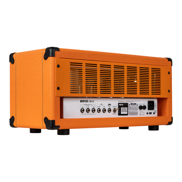
Valve-Buffered Effects Loop
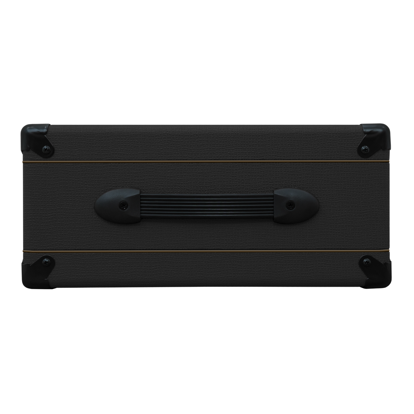
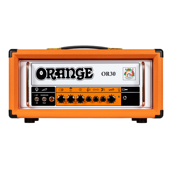
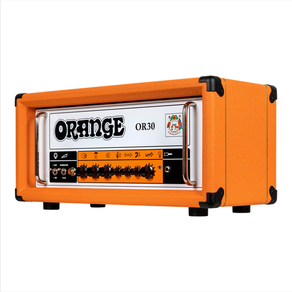
Iconic Orange Styling
Collapsible content
Full Specification
Manuals
In More Detail
Don’t be fooled by the size: the Orange OR15 is a serious amp for serious tone-chasers. Based on the legendary “Pics & Text” amps of the early 70s, it brings that unmistakable Orange growl into a compact format, with enough gain on tap to cover everything from blues and classic rock to modern grit. Its simple layout — gain, three-band EQ, and master volume — keeps the focus on the music, not the menu.
The OR15’s all-valve signal path oozes warmth and touch sensitivity, while the 15-Watt output can be dropped to 7 Watts for home use or saturated studio tones at manageable volumes. Add in a fully valve-buffered effects loop, and you’ve got an amp that’s as versatile as it is vibey. Rugged and reliable, the OR15 is a go-to head for vintage character with modern control.
Headroom v bedroom
The OR15 gives you genuine valve headroom when you want it, and the freedom to scale down when you don’t. Switch from 15 to 7 Watts and get natural power-amp break-up at lower volumes, ideal for home use or recording. Crank it to 15 Watts for more punch and presence on stage. However you use it, the OR15 retains its character, dynamics, and touch sensitivity, proving that full-fat tone doesn’t have to come with deafening volume.
Valve-buffered effects loop
The OR15 features a proper valve-driven effects loop, giving you the headroom and clarity needed for your pedals to shine. Whether you’re running ambient reverbs, crisp delays, or modulation-heavy effects chains, they’ll all stay tight, musical, and free from tone loss. This loop is designed to handle it all without compromising the amp’s raw valve tone, making it perfect for modern pedalboards and analogue purists alike.
Design classic
With its plexi-style control panel, vintage-inspired layout, and unmistakable Orange visuals, the OR15 pays homage to the golden age of British amplification. But it’s not just about looks. The circuit design, based on our iconic “Pics & Text” amps, delivers that same fat, mid-rich voicing that put Orange on the map in the first place. Handmade in the UK with modern build quality and vintage tone at heart, the OR15 is living proof that great design never goes out of style.
Listen Yourself


Built to Perform
Tour-tough, gig-ready and made with premium components, all Orange equipment is built for a lifetime on the road or in the studio.
Iconic British Tone
From classic crunch to modern pristine chime, the unmistakable Orange sound is rich, responsive and full of character.


Instantly Recognisable
Our bold design, including the classic pics-only controls and signature orange tolex finish, have made us a stage and studio icon for half a century.