


Crush Acoustic 30
Crush Acoustic 30
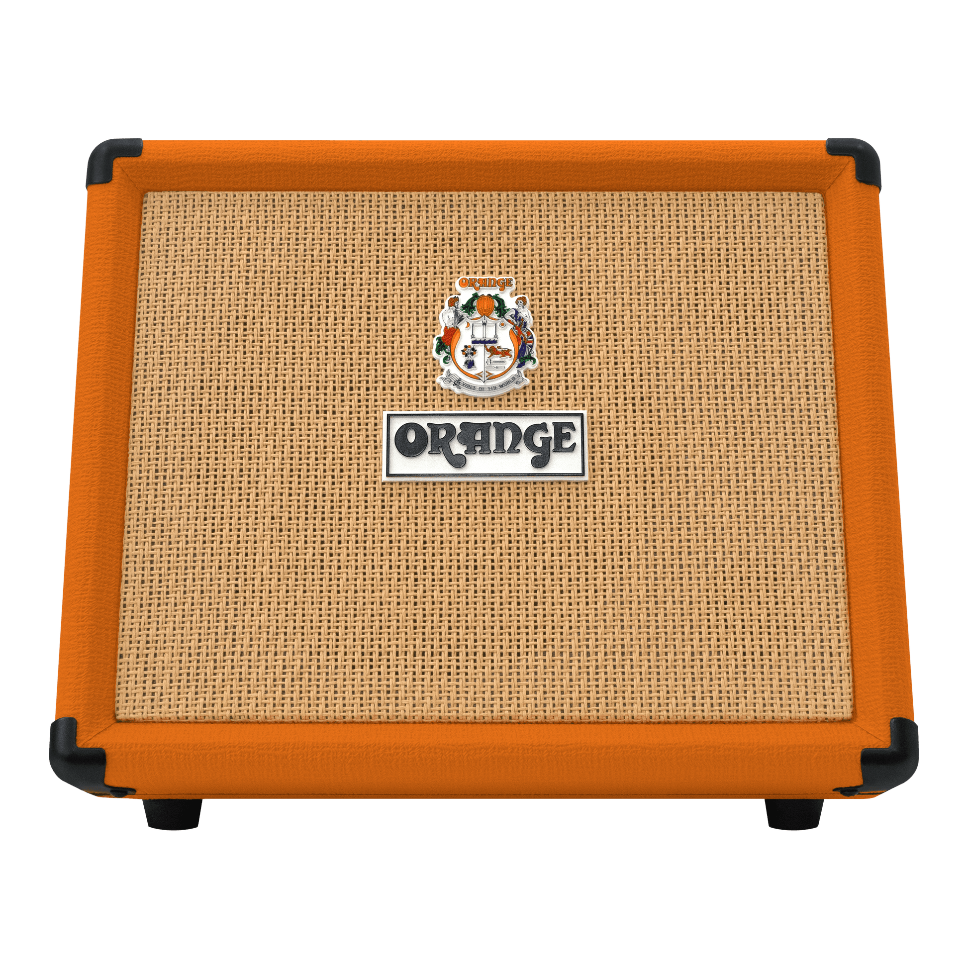
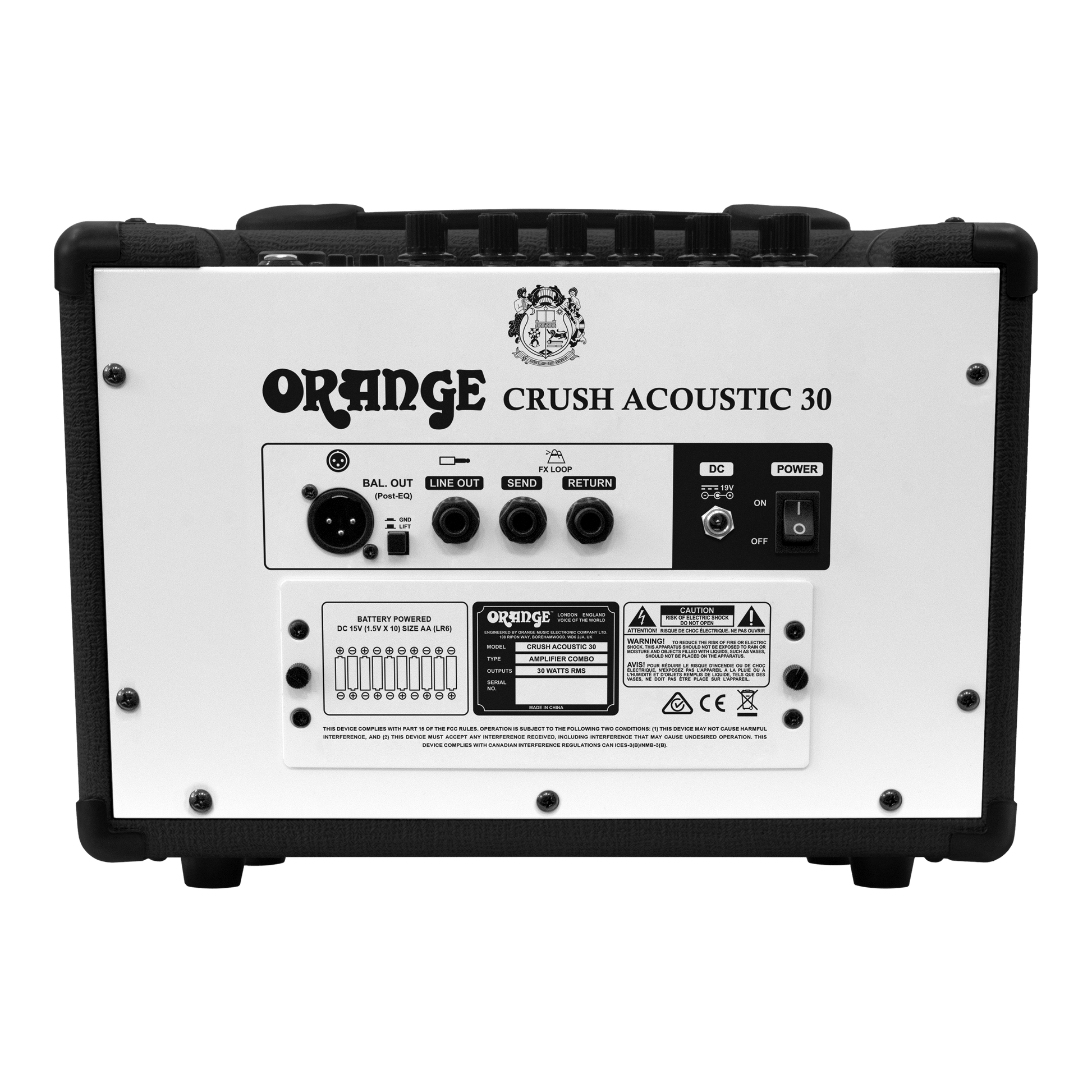
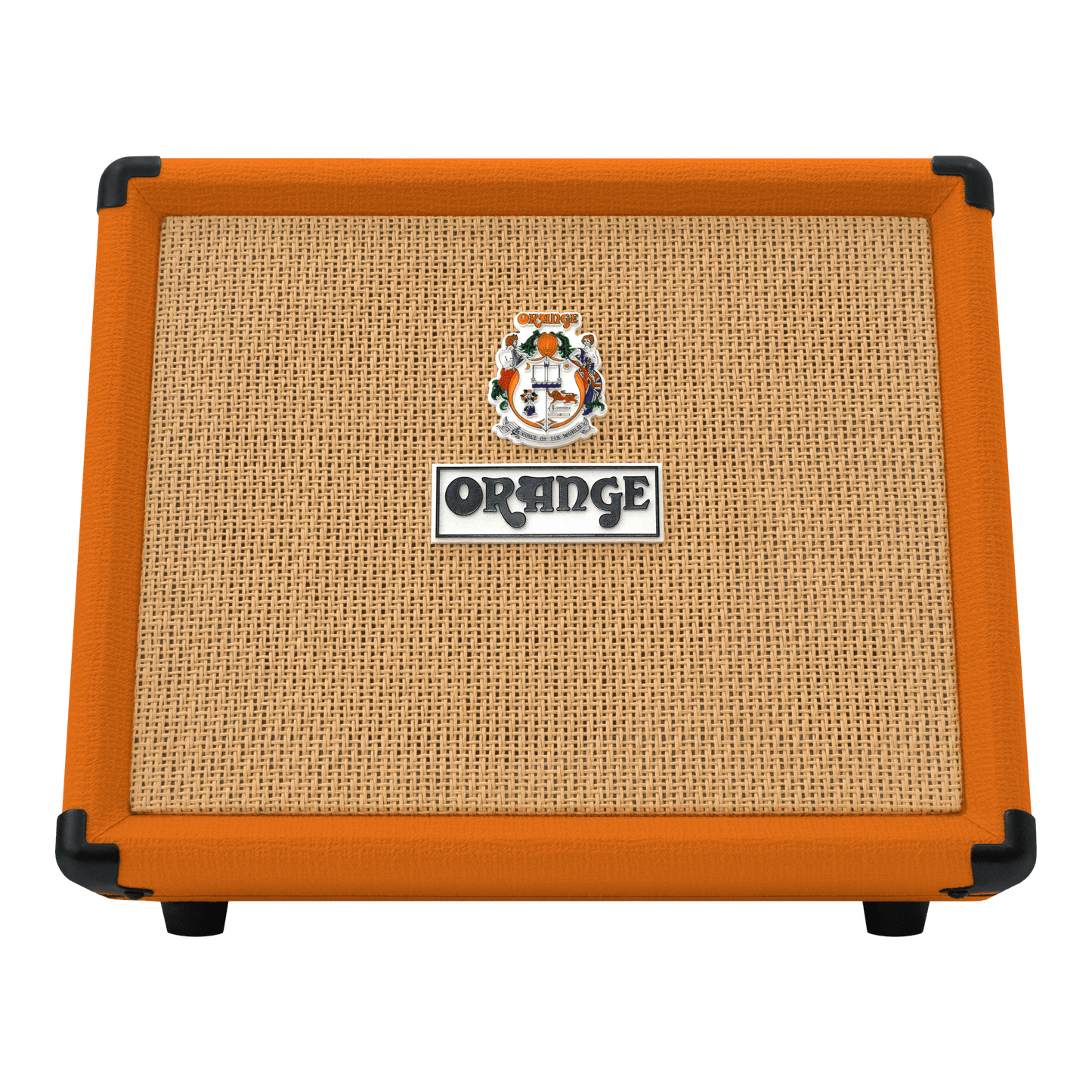
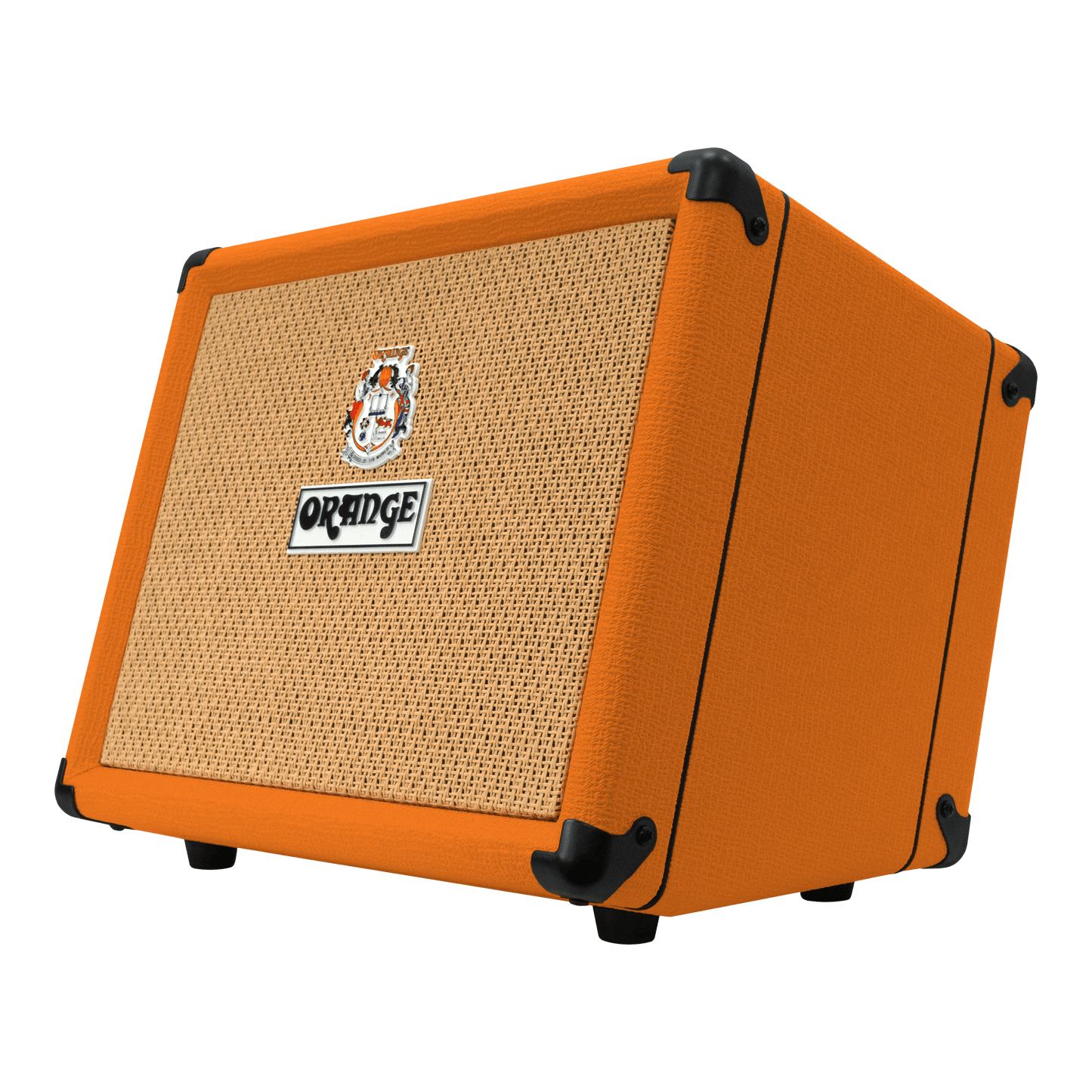
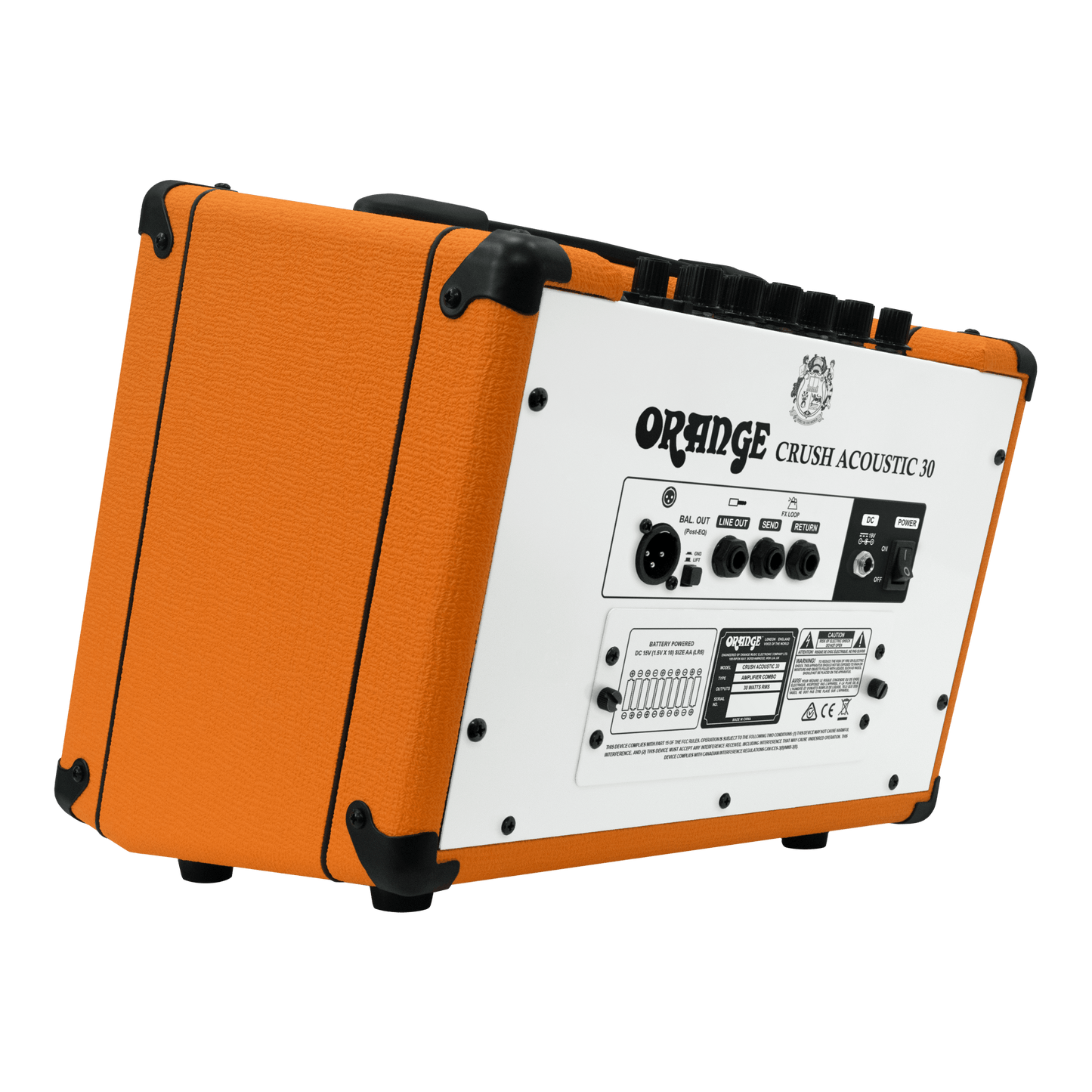
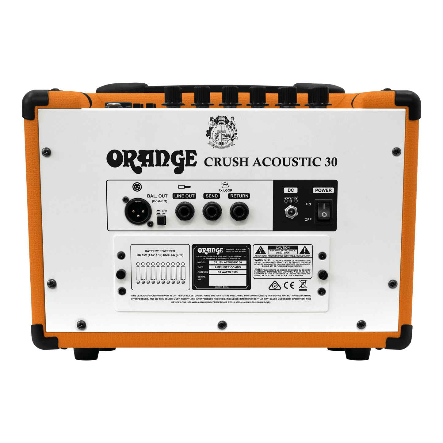
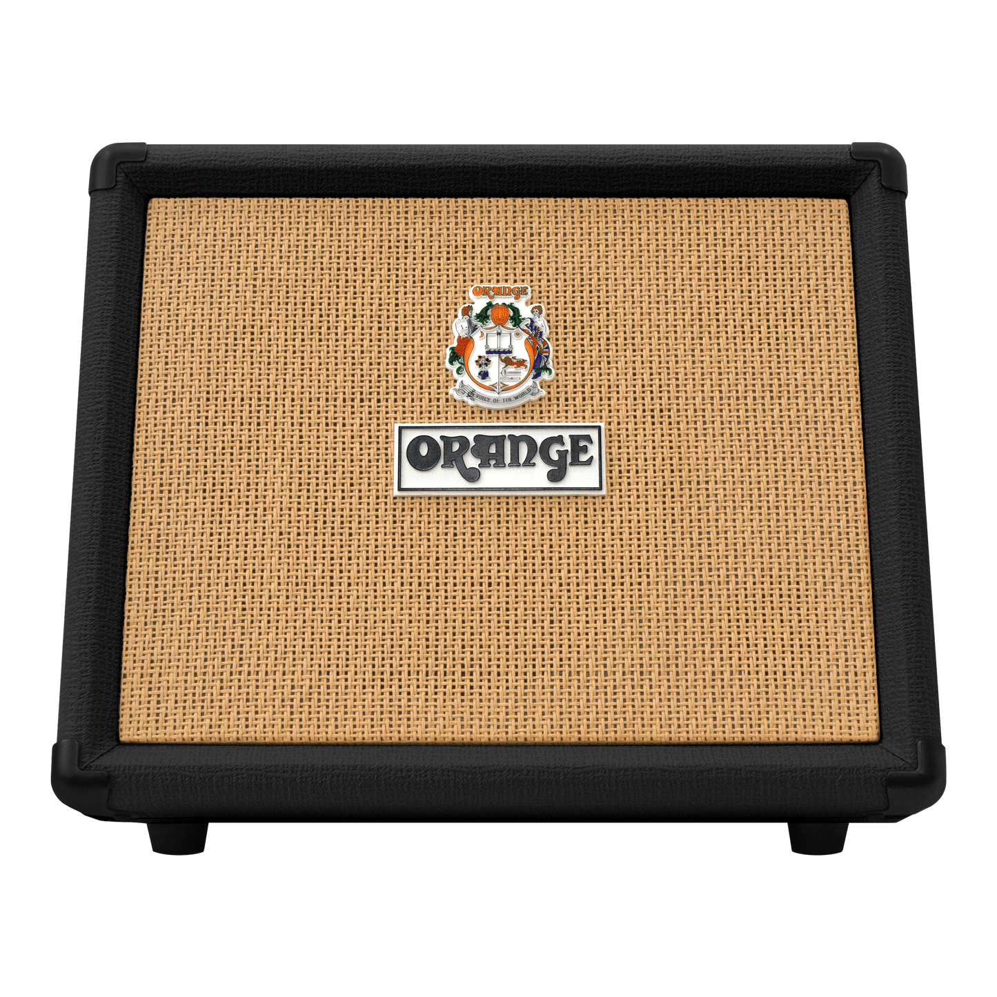
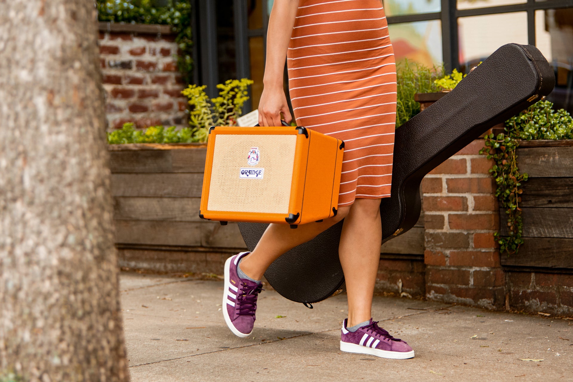
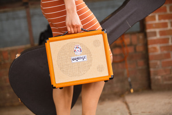
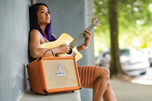
The Orange Crush Acoustic 30 is a compact 30-Watt amplifier designed specifically for acoustic guitarists and vocalists on the move. Featuring independent instrument and mic channels, each with its own EQ and volume control, it ensures crystal‑clear sound and feedback-free performance. The global effects section includes chorus, reverb and a notch filter to sculpt out unwanted resonances. Run it from the mains or on batteries for true portability. Balanced XLR and line outs makes recording a snip, and a buffered effects loop keeps all pedals sounding crisp. With rugged construction and unmistakable Orange character, the Crush Acoustic 30 delivers all you need for flawless acoustic amplification anywhere.


Dual Instrument and Mic Channels
Built‑In Chorus & Reverb
Adjustable Notch Filter
Battery or Mains Operation
Collapsible content
Full Specification
Manuals

In More Detail
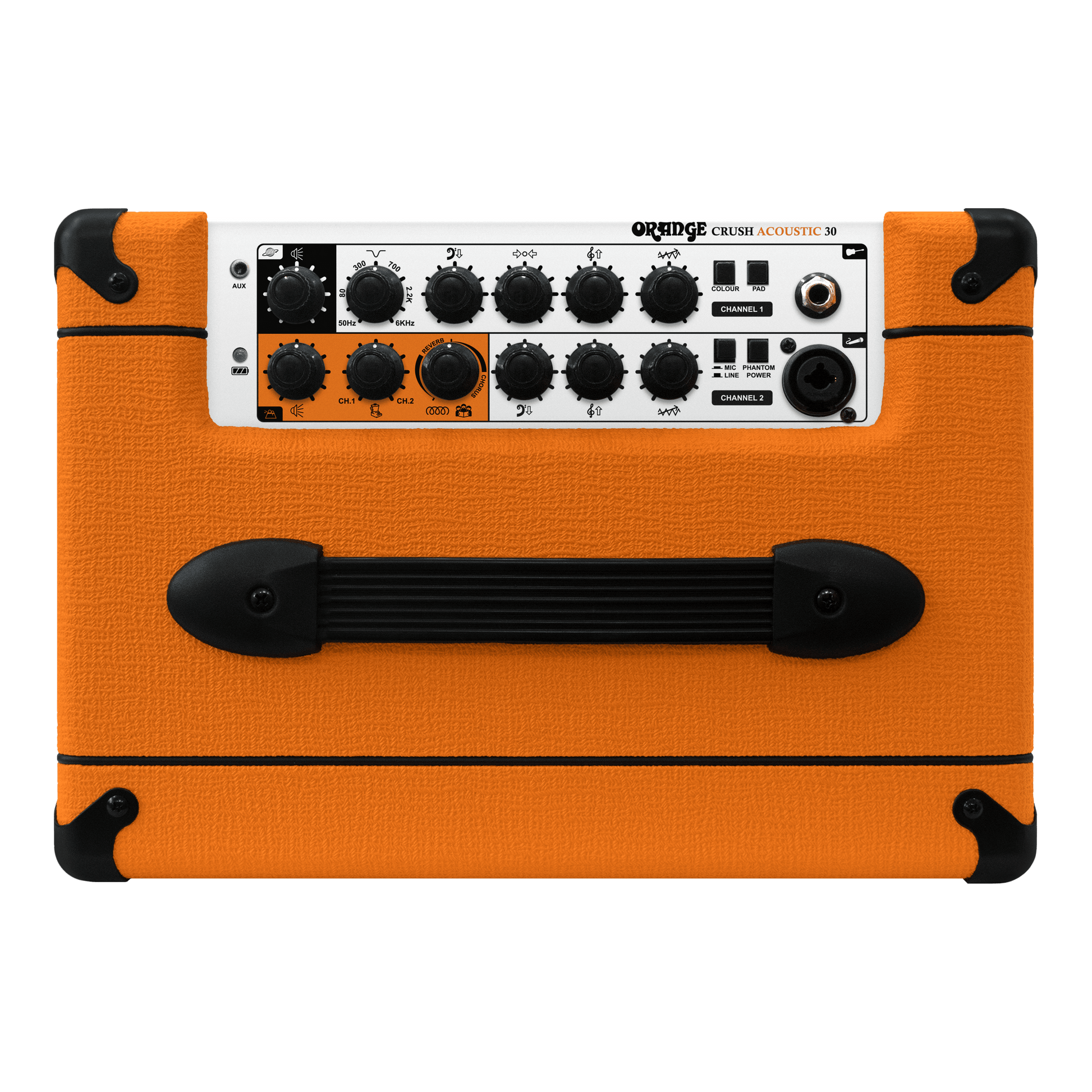
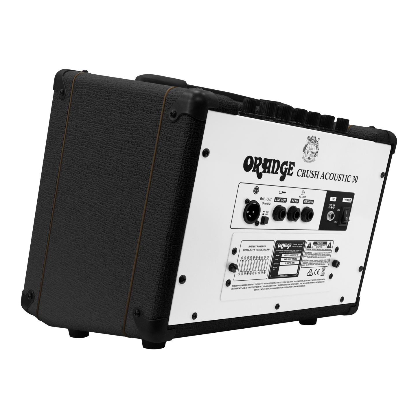
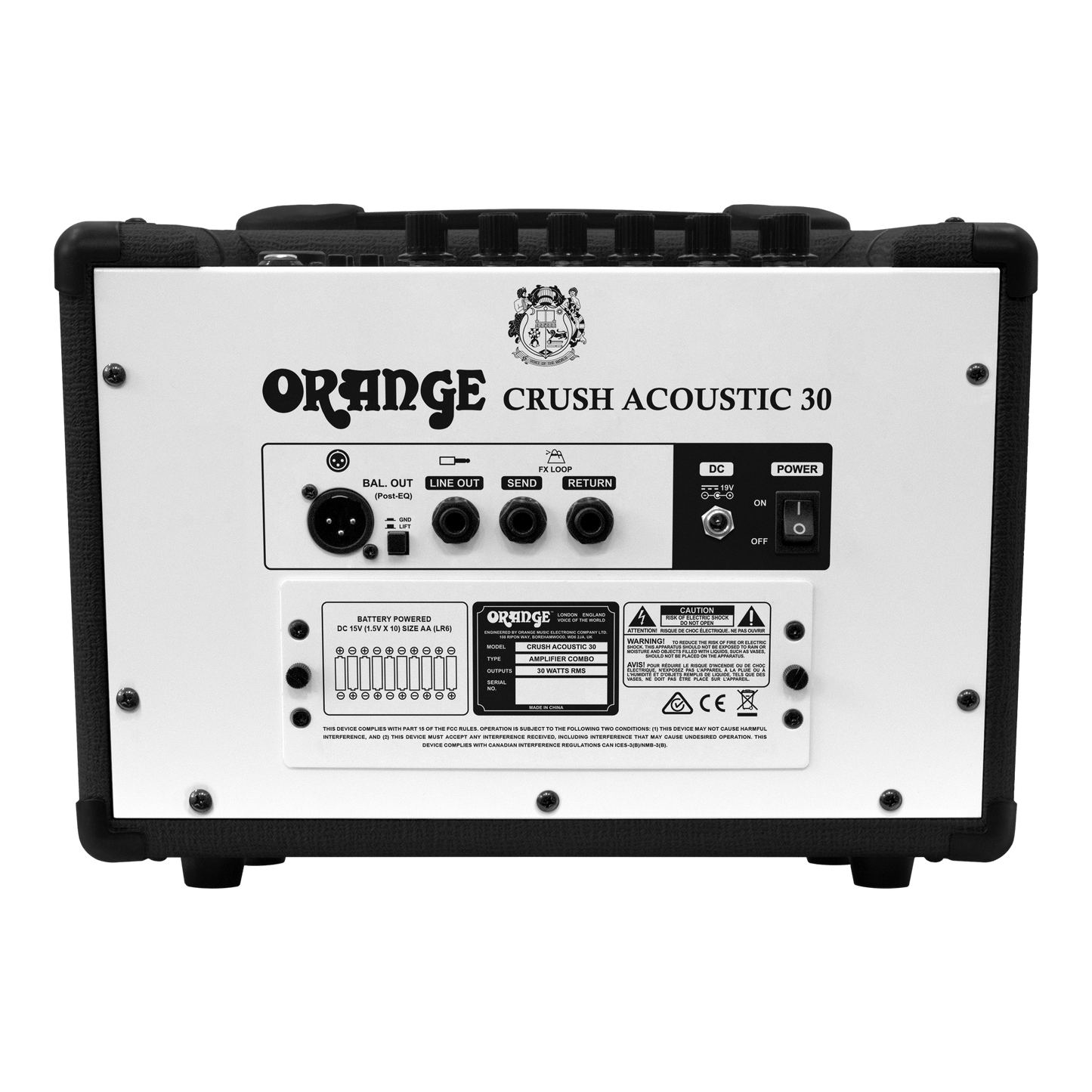
The Crush Acoustic 30 delivers 30 watts of pristine, uncoloured amplification in a lightweight chassis. Its dual‑channel layout gives you both a high‑impedance instrument input, complete with 3‑band EQ tailored for guitar, and a low‑impedance XLR mic input with dedicated preamp and EQ section. The global effects section offers lush chorus and spacious reverb, plus an adjustable notch filter that tames feedback and room resonances.
Switch between mains and battery power, with ten AA batteries providing up to ten hours of uninterrupted performance. Finished with a line or XLR out for plugginging into a PA or recording, and an aux‑in for backing tracks, the Crush Acoustic 30 is equally suited to coffee‑shop gigs, busking, or home studio work. All this comes in a road‑worthy Orange package built to last.
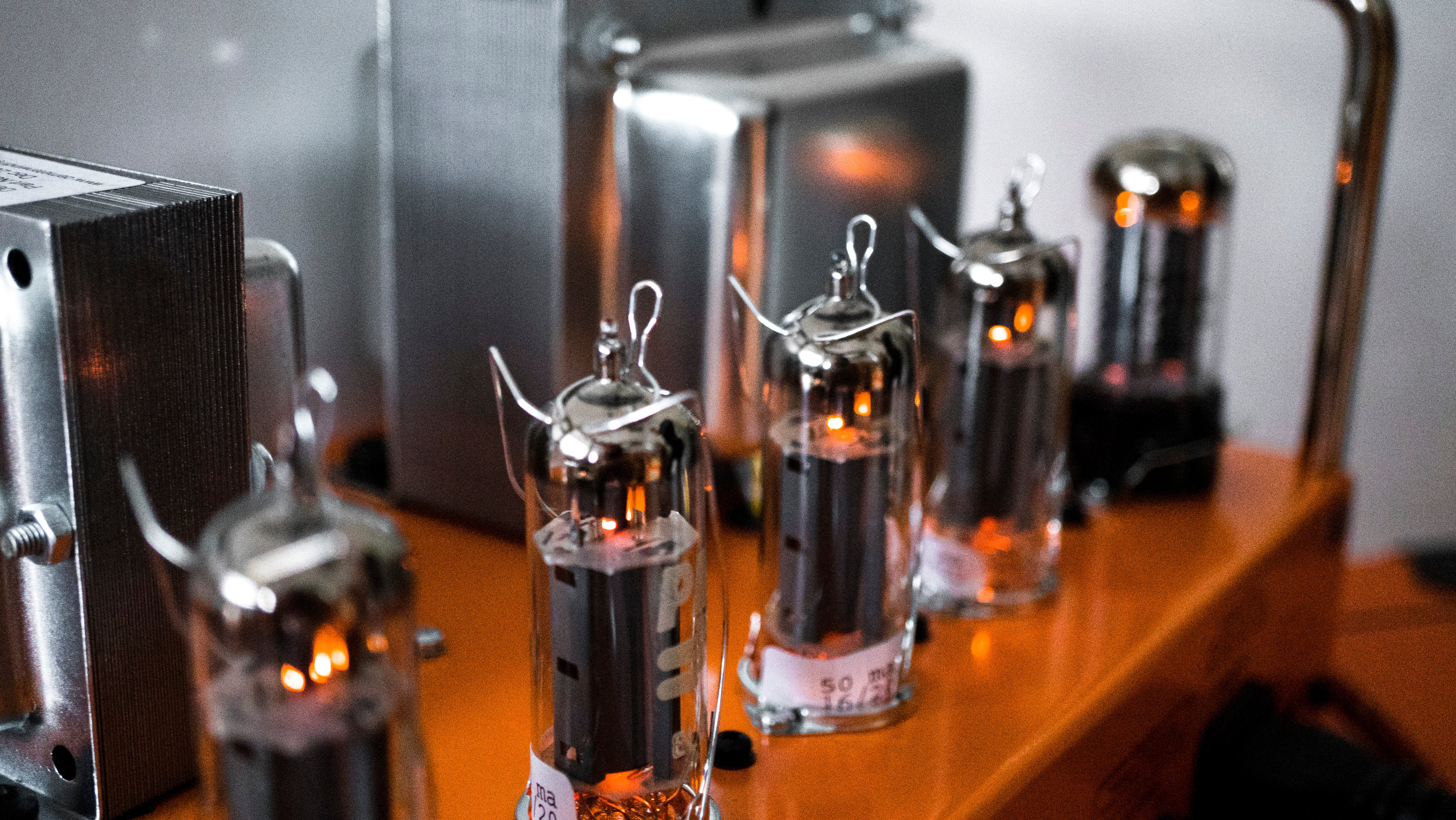
All-analogue signal path
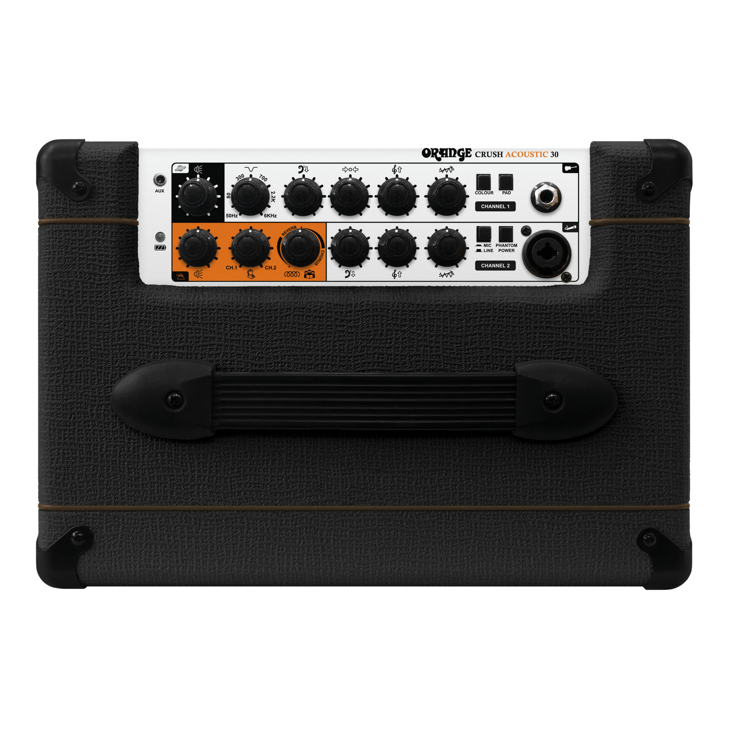
Crush Acoustic 30 gives you two dedicated signal paths: a high‑impedance guitar channel and a low‑impedance XLR mic channel. Each path features its own EQ and gain stage, guaranteeing optimal clarity and control for both your acoustic guitar’s natural tone and your vocal performance.
Global effects and notch filter
Enhance your sound with built‑in chorus and reverb, designed to add dimension without masking your instrument’s character. The variable notch filter zeros in on feedback‑prone frequencies, giving you confident, feedback‑free playing even in the trickiest acoustic environments. It’s the fast, effective way to polish your live tone.
Battery-powered
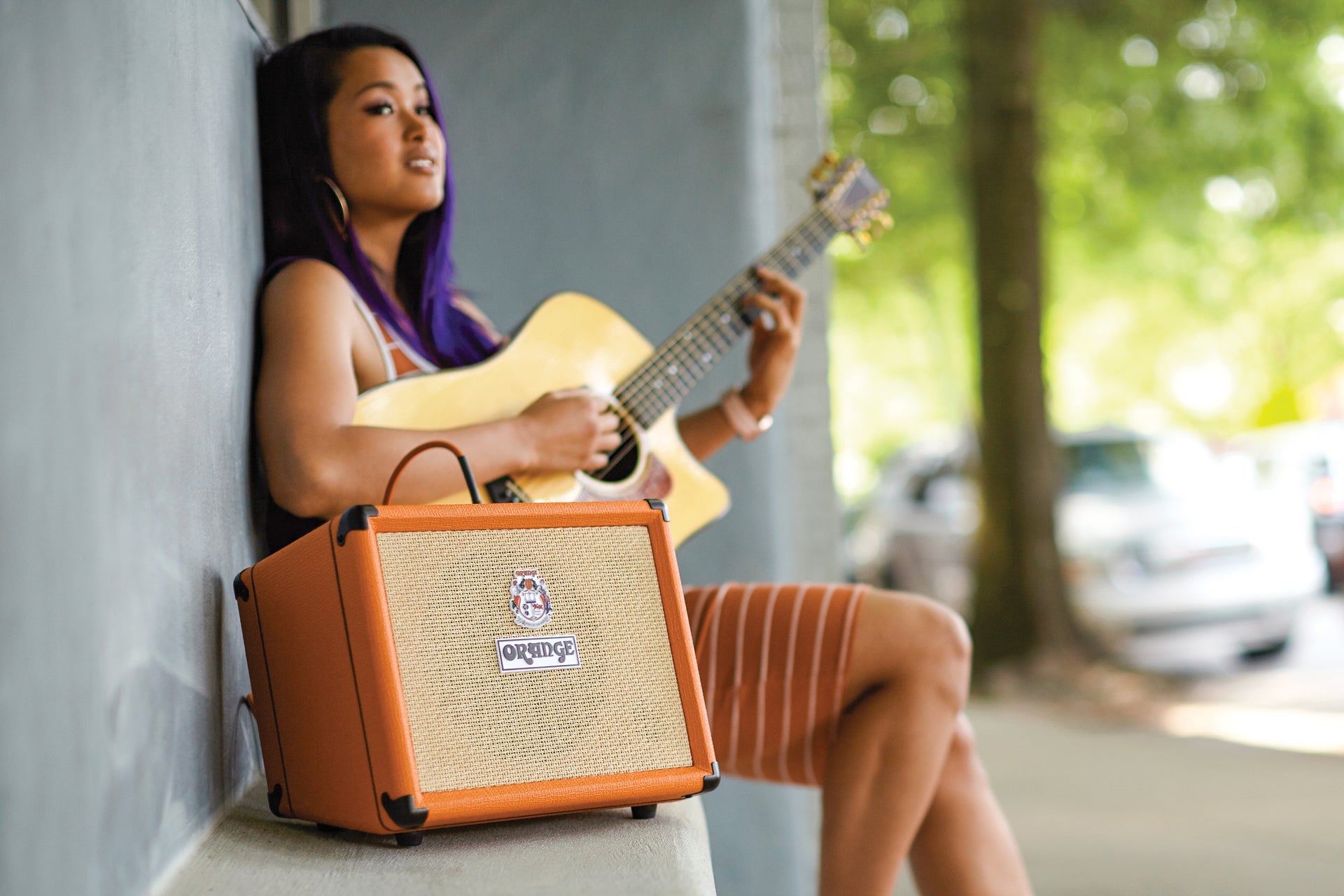
Whether you’re busking on the street, playing in a park, or jamming where cables can’t reach, the Crush Acoustic 30 has you covered. Ten AA batteries deliver up to ten hours of reliable, mains‑free performance. Lightweight, compact, and utterly portable, this amp keeps you playing wherever inspiration strikes.


You may also like


Built to Perform
Tour-tough, gig-ready and made with premium components, all Orange equipment is built for a lifetime on the road or in the studio.
Iconic British Tone
From classic crunch to modern pristine chime, the unmistakable Orange sound is rich, responsive and full of character.


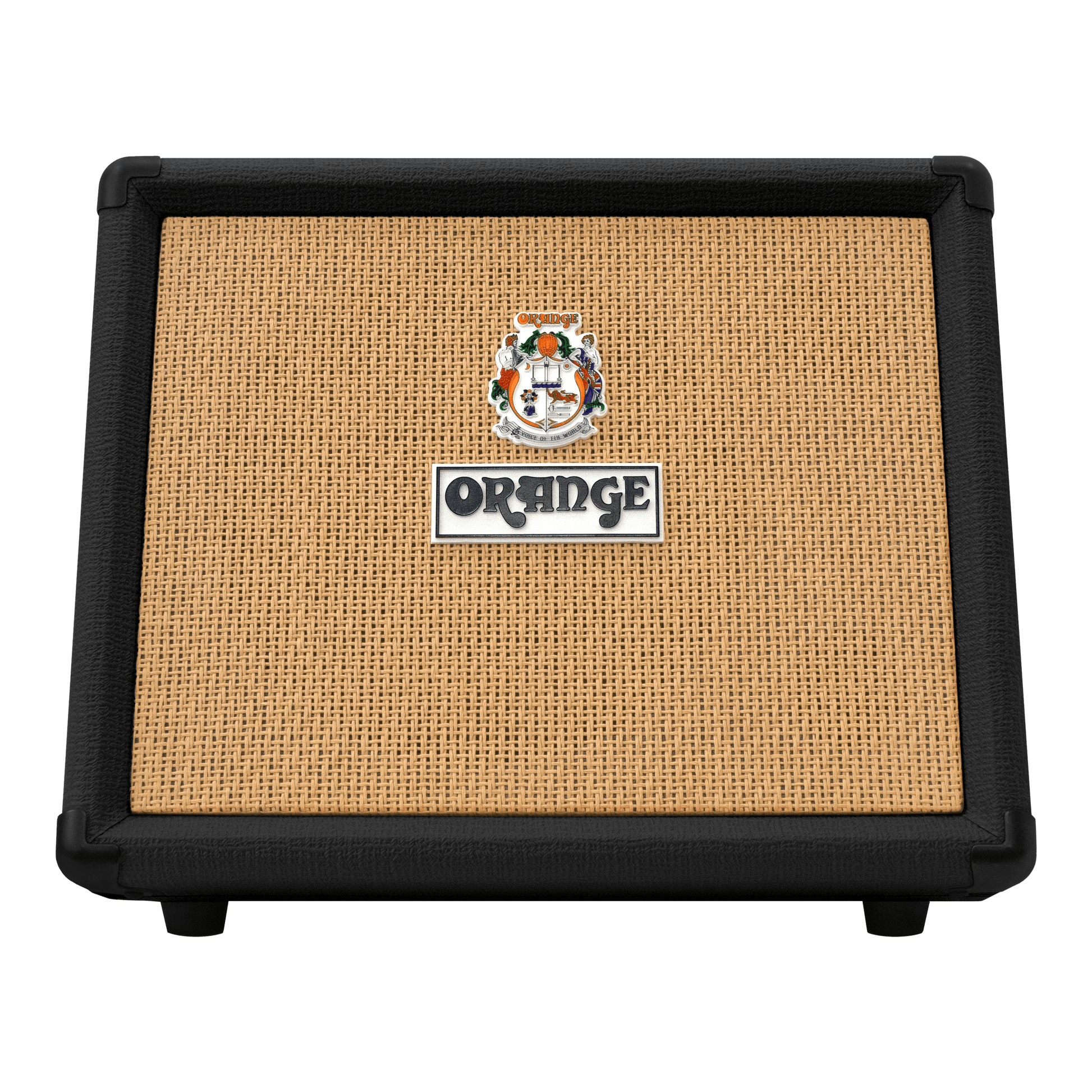
Instantly Recognisable
Our bold design, including the classic pics-only controls and signature orange tolex finish, have made us a stage and studio icon for half a century.